
For my application I need an accurate voltage measurement up to 36V.
And I also I want to upload those measurements to a server via WIFI. I've bought a RP2040 with a display for this task: 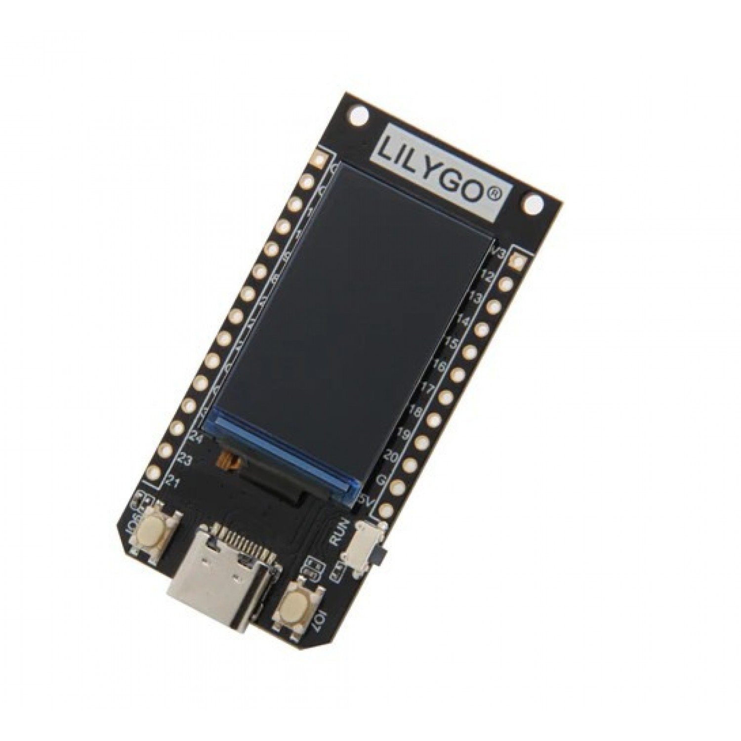
To achieve acurate measurements I decided to try the INA226, which you can buy already mounted on a small PCB and has a I2C interface: 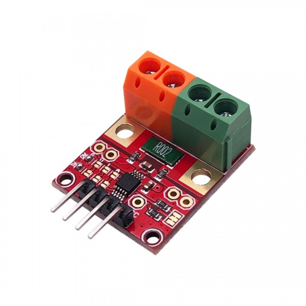
The hardware setup is fairly straight forward, I power the INA226 from the RP2040 and connect the SCL (pin 13) and SDA (pin 12) and you are done, and end up with something like this: 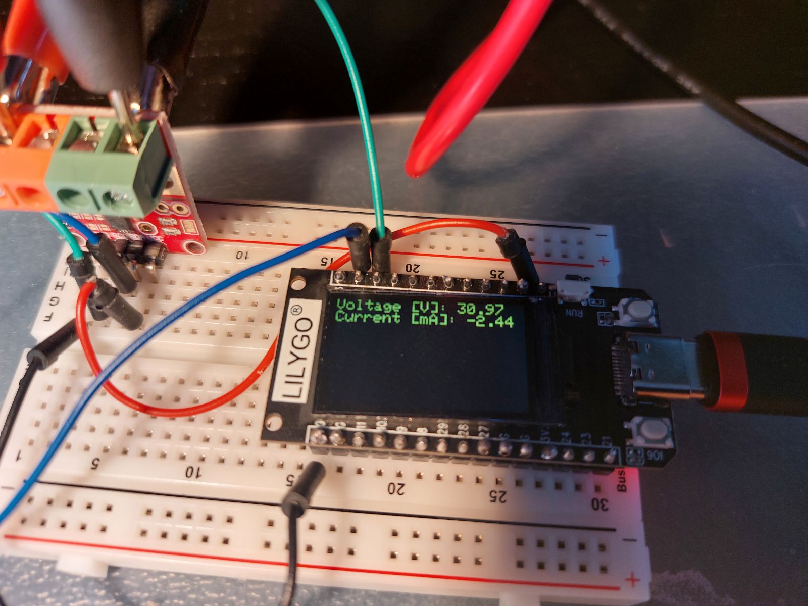
Looking at the PSU: 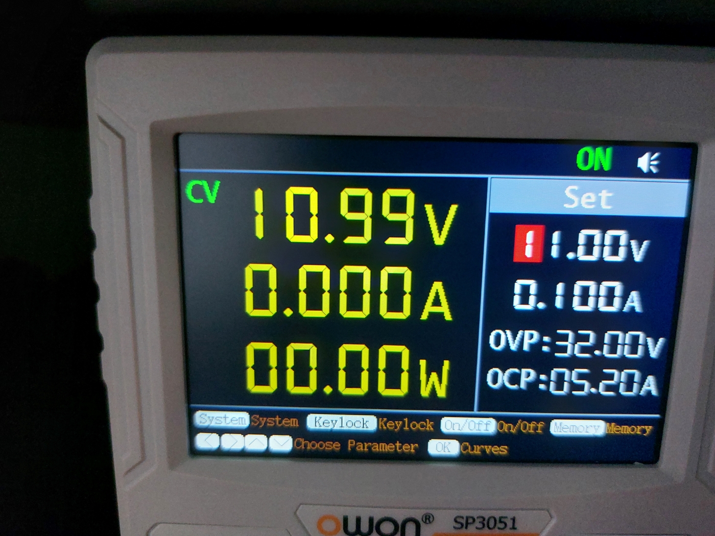
And comparing the INA226, the measurement does indeed seem to be very acurate: 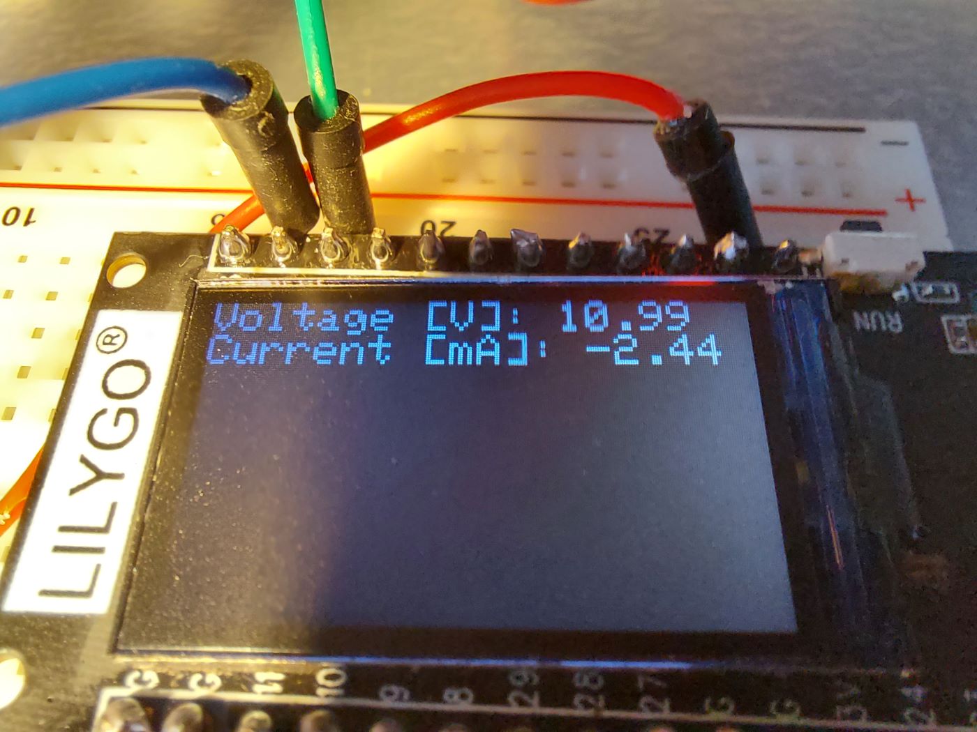
Also a double check measurement with my Fluke shows acurate results: 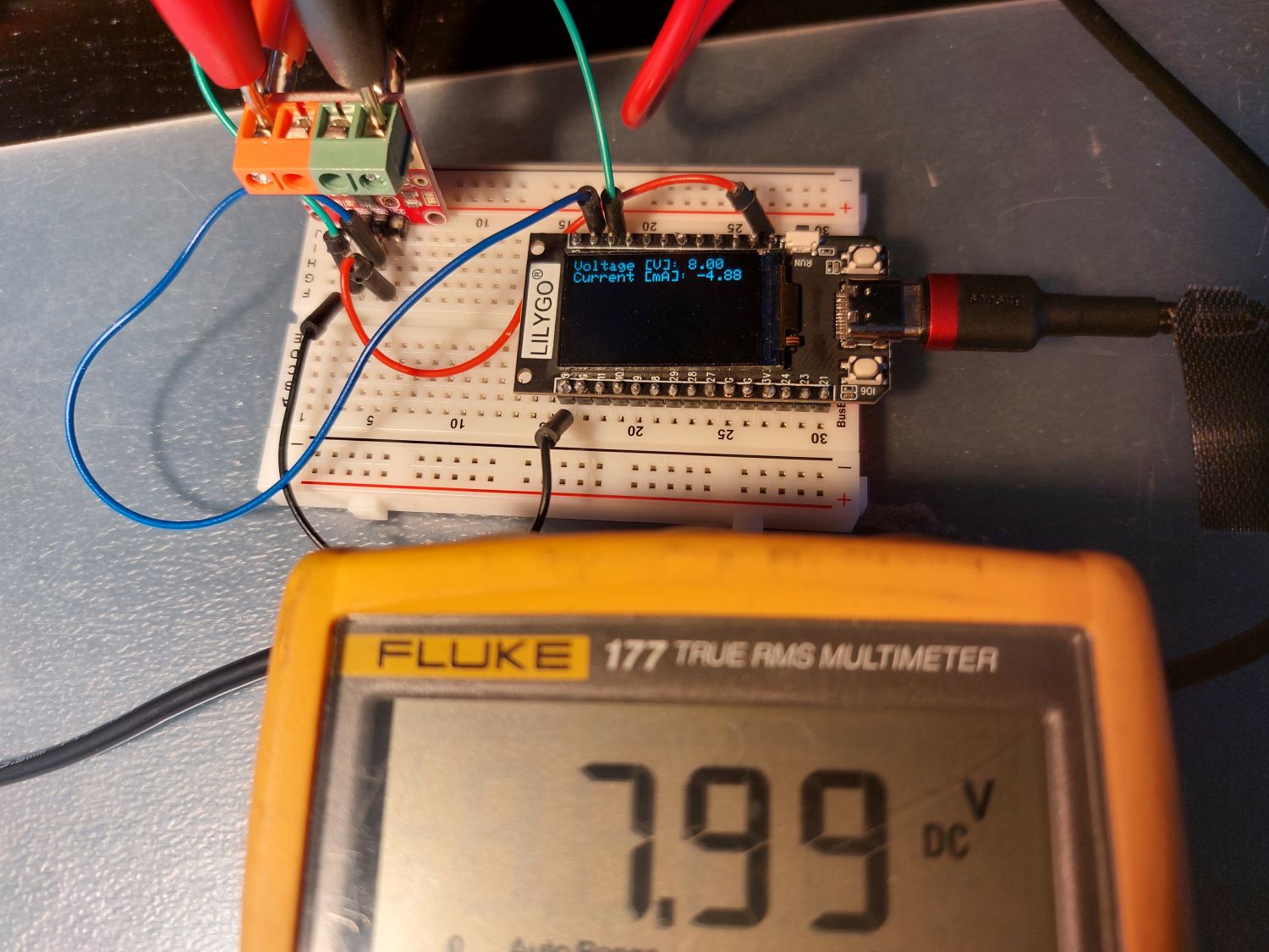
I used the Arduino IDE to program the RP2040 using this code:
#include <TFT_eSPI.h> //tested with v2.4.78 from https://github.com/Xinyuan-LilyGO/LILYGO-T-display-RP2040
#include <stdio.h>
#include "pico/stdlib.h"
#include <Arduino.h>
#include "hardware/gpio.h"
#include <Wire.h>
#include <INA226_WE.h>

/*
#define TFT_MISO -1
#define TFT_MOSI 3
#define TFT_SCLK 2
#define TFT_CS 5  // Chip select control pin
#define TFT_DC 1  // Data Command control pin
#define TFT_RST 0 // Reset pin (could connect to RST pin) */
#define TFT_BL 4
#define PWR_ON 22
#define BOTTON1 6
#define BOTTON2 7
#define RedLED 25
#define BatVol 26
#define I2C_SDA 12
#define I2C_SCL 13
#define I2C_INA_ADDRESS 0x40


#define dark()                   \
  for (int i = 0xff; i > 0; i--) \
  {                              \
    delay(5);                    \
    analogWrite(TFT_BL, i);      \
  }                              \
  digitalWrite(RedLED, !digitalRead(RedLED));

#define light()                  \
  for (int i = 0; i < 0xff; i++) \
  {                              \
    delay(5);                    \
    analogWrite(TFT_BL, i);      \
  }                              \
  digitalWrite(RedLED, !digitalRead(RedLED));

TFT_eSPI tft = TFT_eSPI();

INA226_WE ina = INA226_WE(&Wire);

void setup()
{
  pinMode(PWR_ON, OUTPUT);
  digitalWrite(PWR_ON, 1);
  pinMode(BatVol, INPUT);
  pinMode(TFT_BL, OUTPUT);
  pinMode(RedLED, OUTPUT);
  digitalWrite(TFT_BL, 0);
  analogWrite(TFT_BL, 0);

  Serial.begin(115200);
  tft.init();
  tft.setRotation(1);
  tft.setTextSize(2);
  tft.setSwapBytes(true);
  light();
  Serial.println("Hello Pico");

  Serial.println("I2C init: SDA 12 SCL 13");
  Wire.setSDA(I2C_SDA);
  Wire.setSCL(I2C_SCL);
  Wire.begin();
  delay(500);

  Serial.println("Initialize INA226");

  // Default INA226 address is 0x40
  bool success = ina.init();

  // Check if the connection was successful, stop if not
  if(!success)
  {
    Serial.println("Connection error");
    while(1);
  }

  // Configure INA226
  ina.setResistorRange(0.002,20.0);

  ina.waitUntilConversionCompleted();
  Serial.println("-----------------------------------------------");
  tft.fillScreen(TFT_BLACK);
}

void loop()
{

  float shuntVoltage_mV = 0.0;
  float busVoltage_V = 0.0;
  float current_mA = 0.0;
  float power_mW = 0.0;

  ina.readAndClearFlags();
  shuntVoltage_mV = ina.getShuntVoltage_mV();
  busVoltage_V = ina.getBusVoltage_V();
  current_mA = ina.getCurrent_mA();
  power_mW = ina.getBusPower();

  Serial.print("Shunt Voltage [mV]: "); Serial.println(shuntVoltage_mV);
  Serial.print("Bus Voltage [V]: "); Serial.println(busVoltage_V);
  Serial.print("Current[mA]: "); Serial.println(current_mA);
  Serial.print("Bus Power [mW]: "); Serial.println(power_mW);
  if(!ina.overflow){
    Serial.println("Values OK - no overflow");
  }
  else{
    Serial.println("Overflow! Choose higher current range");
  }
  Serial.println();

  tft.fillScreen(TFT_BLACK);
  tft.setCursor(0, 0);
  tft.setTextColor(random(TFT_WHITE));
  tft.print("Voltage [V]: ");
  tft.print(busVoltage_V);
  tft.println();

  tft.print("Current [mA]: ");
  tft.print(current_mA);

  delay(1500);
      }
Hope this helps.